Call Us Today! (503) 848-6190 | info@elwellcorp.com

Gold Heat Quick Installation Guide - Gold Heat

This guide will help you install your new Gold Heat system safely and efficiently.

If you have any questions before, during, or after installation, please call us at (877) 789-4328 between 6:00 am and 3:30 pm PST.


Things to Know

  • This Gold Heat mat is customized for your floor plan and ready to install. Do not attempt to modify the Gold Heat mat or its wiring before, during, or after installation.
  • Gold Heat mats must be installed on a circuit protected with a Ground Fault Circuit Interrupter (GFCI). Verify that your thermostat, control panel, or circuit breaker includes GFCI protection prior to installation.
  • Do not install Gold Heat mats under walls or cabinets.
  • Gold Heat mats should never overlap one another, and predesigned wire spacing must be maintained.
  • Never cut or bend the wires in your Gold Heat mat. If the wires are accidentally damaged, please refer to the Gold Heat Wire Repair Instructions.

Tools Required for Installation

  • Multimeter

  • Staple gun

  • LoudMouth Installation Monitor

  • Marker

  • Chisel or router

  • Tape or hot melt glue gun

Getting Started

1. Clean the subfloor of all debris.

Make sure there are no protruding objects such as nails or staples that could damage the Gold Heat mat or wires.

2. Spread out the Gold Heat mat on the subfloor.

(a) Make sure the wires are on the underside of the mat (facing the subfloor), with the fabric mesh on top (facing the ceiling).

(b) Do not staple or anchor the mat yet.

3. Inspect the mat.

(a) Check the entire mat for size and fit, making sure there is no interference with walls, floor heating vents, or other objects.

(b) If the wires are damaged or separated from the fabric mesh, stop installation and refer to the Gold Heat Wire Repair Instructions.

4. Perform electrical test #1.

(a) Locate the Gold Heat product label near the end of the cold lead, which indicates the standard resistance of your heating mat (Gold Heat resistance ranges from 9-150 ohms, depending on the size of the mat).

(b) Use a multimeter on the ohms () setting to test the resistance of the heating wire.

— White-to-black resistance should be within 10% (+/-) of the standard resistance indicated on the Gold Heat product label. (Figure 1)

— White-to-ground resistance should be infinite, typically indicated by OL (Over Limit). (Figure 2)

— If either condition is not true, stop installation and contact Gold Heat technical support for troubleshooting assistance.

5. Attach installation monitor. (Figure 3)

(a) Attach a LoudMouth installation monitor to the Gold Heat cold lead and turn it on.

(b) Leave the monitor on throughout the installation.

(c) If the alarm sounds at any time, stop installation and contact Gold Heat technical support for troubleshooting assistance.

Gold Heat Quick Installation Guide - Gold Heat

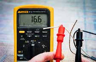
Figure 1. Verify that resistance matches the value on the product label.

Gold Heat Quick Installation Guide - Gold Heat

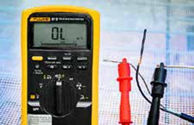
Figure 2. Confirm no continuity to ground wire.

Gold Heat Quick Installation Guide - Gold Heat

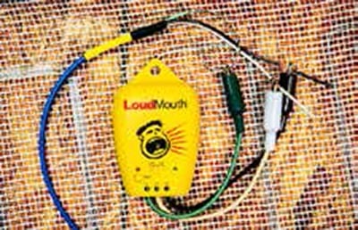
Figure 3. Your LoudMouth will alert you immediately of any damage to the wire.

Embedding the Components

Embedding the components in the subfloor ensures the thinnest, flattest installation.

Steps 6 and 7 are optional when installing Gold Heat mats on concrete floors.

6. Outline the components.

(a) Using a marker, draw outlines for the cold lead and cold lead splice on the subfloor. (Figure 4)
(b) If your Gold Heat system includes a temperature sensor, position the sensor and outline its location. Optimal placement is:

— Between heating wires
— At least 4 from the edge of the mat
— At least 12 away from furnace vents and other heat sources

7. Create space for the components.

(a) Carefully pull back the Gold Heat mat to fully expose the outlined areas of the subfloor. (Figure 5)
(b) Using a marker, fill in the outlines.
(c) Using a chisel or router, hollow out the highlighted areas of the subfloor (1/4 deep). (Figure 6 and Figure 7)

Gold Heat Quick Installation Guide - Gold Heat

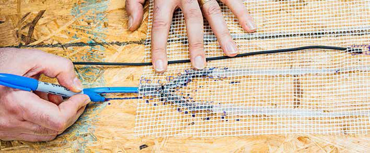
Figure 4. Outlining the components.

Gold Heat Quick Installation Guide - Gold Heat

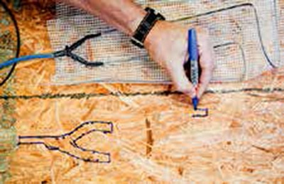
Figure 5. Outline the cold lead splice and sensor location.

Gold Heat Quick Installation Guide - Gold Heat

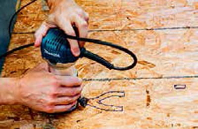
Figure 6. Use a router or chisel to relieve the subfloor 1/4″ deep.

Gold Heat Quick Installation Guide - Gold Heat

Figure 7. These pockets ensure the thinnest, flattest installation.

Anchoring the Mat

8. Anchor the temperature sensor.

(a) If your Gold Heat system includes a temperature sensor, secure it to the subfloor with hot glue or tape in the predetermined location (see steps 6-7).
(b) Run the sensor wire to the edge of the work area. (Figure 8)

9. Anchor the cold lead and cold lead splice.

(a) Return the Gold Heat mat to its final position.
(b) Secure the cold lead and cold lead splice to the subfloor with hot glue or tape in their predetermined locations (see steps 6-7). (Figure 9)
(c) Make sure the Gold Heat mat is adequately flat before continuing installation.

10. Anchor the Gold Heat mat.

(a) Staple through the fabric only. DO NOT staple into or across the heating wires or cold lead. (Figure 10)
(b) Using a staple gun, secure the Gold Heat mat to the subfloor.

— Anchor the area around the cold lead splice first.
— Next, run a line of staples down the center of the mat.
— Working from the center out, apply a gentle tension and staple down the rest of the heat mat.
— A grid pattern is recommended, with staples no more than 12 apart. (Figure 11)

11. Perform electrical test #2.

(a) Check the installation monitor.
(b)  If the installation monitor is no longer plugged into the cold lead or not showing a green light, repeat the electrical tests from step 5.

Gold Heat Quick Installation Guide - Gold Heat

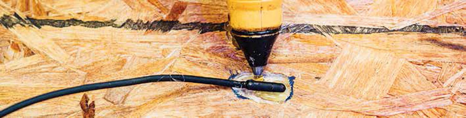
Figure 8. Secure the temperature sensor to the subfloor.

Gold Heat Quick Installation Guide - Gold Heat

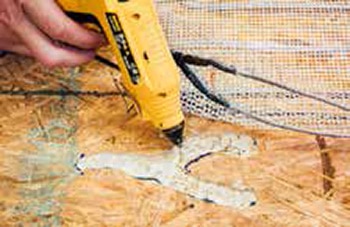
Figure 9. Secure the cold lead and cold lead splice to subfloor.

Gold Heat Quick Installation Guide - Gold Heat

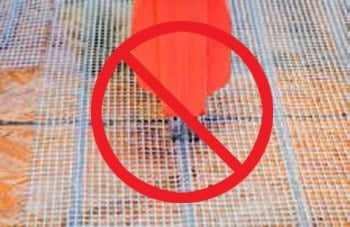
Figure 10. Staple through fabric only. Do NOT staple into or across the heating wires or cold   lead.

Gold Heat Quick Installation Guide - Gold Heat

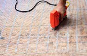
Figure 11. Staple in a grid pattern, no more than 12″ apart.

For concrete floors, Gold Heat mats can be anchored with any fast-setting adhesive, tape or concrete floor fastener.

Installing the Tile

12. Install floor tile using standard materials.

(a) Do not strike a trowel against the floor to dislodge tile setting compound. This can damage the heating wires.
(b) Using the flat edge of a trowel, press the setting compound through the Gold Heat fabric mesh for maximum adhesive binding.
(c) Add additional setting compound as needed and comb to ensure uniform application (at least 3/8 deep). (Figure 12)
(d) If using an anti-fracture membrane, place the membrane over the Gold Heat mat after the compound has been applied. DO NOT staple through an anti- fracture membrane into the heating wires.

13. Perform electrical test #3.

(a) Check the installation monitor.
(b) If the installation monitor is no longer plugged into the cold lead or not showing a green light, repeat step 5.

Gold Heat Quick Installation Guide - Gold Heat

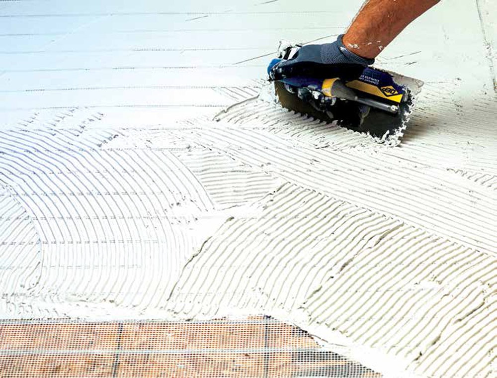
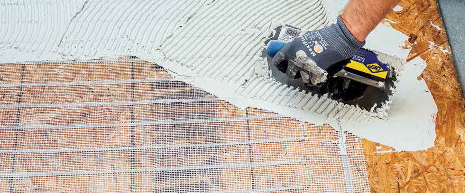
Figure 12. Press the setting compound through the fabric mesh to wet out the subfloor, then add compound as necessary and comb up a setting bed.

Final Steps

14. Affix labels.

(a) Affix the enclosed Radiant Heat adhesive label to the electrical distribution panel, identifying the branch circuit dedicated to the Gold Heat system.
(b) Affix the Caution and Warning adhesive labels in the room with the heated floor.

15. Continue to monitor.

If possible, leave the installation monitor attached and operating overnight. Use a LoudMouth monitor during grout line cleanup, grout application, and during any tile rework.

16. Connect cold lead.

Connect the cold lead to the thermostat or power module.

17. Cleaning grout lines.

DO NOT use a razor or knife to clean grout lines. (Figure 13)
Clean grout lines with a tool that will not cut the heating wires. (Figure 14)

Gold Heat Quick Installation Guide - Gold Heat

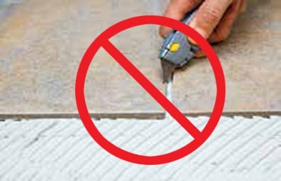
Figure 13. DO NOT use a razor or knife to clean grout lines.

Gold Heat Quick Installation Guide - Gold Heat

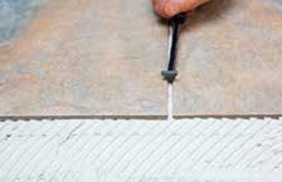
Figure 14. Clean grout lines with a tool that will not harm wires.

ntertek

Operating Notes

Gold Heat is a supplemental heating and comfort feature. Most users find optimal comfort with a floor temperature setting of 78-85F and a forced air furnace setting of around 65F.

Do not place rubber backed rugs, dog beds, blankets, or pillows on heated floor areas. These items trap heat and can create very high tile temperatures, which can damage these materials and create unwanted odors. Fabric throw rugs are recommended.

WARNINGS

RISK OF ELECTRIC SHOCK AND FIRE. DAMAGE TO SUPPLY CONDUCTOR INSULATION MAY OCCUR IF CONDUCTORS ARE ROUTED LESS THAN 2 (51MM) FROM THIS HEATING PRODUCT. REFER TO INSTALLATION INSTRUCTIONS FOR RECOMMENDED MEANS OF ROUTING SUPPLY CONDUCTORS.

THE RADIANT HEATING PANEL SET MUST BE INSTALLED IN ACCORDANCE WITH ARTICLE 424, PART J OF THE NATIONAL ELECTRIC CODE, ANSI/ NFPA 70.

THE INSTALLATION OF THIS HEATING PRODUCT SHALL BE IN ACCORDANCE WITH THE MANUFACTURERS INSTRUCTIONS AND THE REGULATIONS OF THE AUTHORITY HAVING JURISDICTION. FAILURE TO COMPLY WILL VOID THE WARRANTY AND MAY CREATE A HAZARD FOR FIRE OR ELECTRICAL SHOCK.

THIS EQUIPMENT SHALL BE INSTALLED ONLY BY QUALIFIED PERSONNEL WHO ARE FAMILIAR WITH THE CONSTRUCTION AND OPERATION OF THE APPARATUS AND THE RISKS INVOLVED.

FAILURE TO FOLLOW THE INSTRUCTIONS IN THIS MANUAL MAY VOID THE OWNERS WARRANTY ON THE INSTALLED RADIANT HEATING PANEL SET.

THIS PRODUCT IS SOLD AND WARRANTED ONLY FOR PERMANENT INSTALLATION UNDER INTERIOR FLOORING MATERIALS USING A MORTAR BED OR SELF-LEVELING COMPOUND WITH A MINIMUM THICKNESS OF 3/8.

THIS PRODUCT MUST BE CONNECTED TO A GFCI PROTECTED CONTROL DEVICE.

INSTALL BETWEEN 50F AND 120F.